Saturday, 28 April 2018

Electronic Stethoscope using arduino and labview


The microphone is fixed into the diaphram of the stethoscope


Schematic:


Arduino Code:

int mydata=0;
void setup()
{
 pinMode(A0,INPUT);
 Serial.begin(9600);
}

void loop()
{
 
  mydata=analogRead(A0);
  Serial.println(mydata);
  delay(5);
}


lab view block diagram


Lab view front panel:


Diaphram of the stethoscope with microphone                       finished pcb


Smart fuel measurement using arduino uno


The fuel gauge in every bike has the resistance as output,

the variable resistance is connect as pull up and the 1 k resistor is connected as pull down

the variable resistance which is connected to the 1 k resistor is connected  to the A0  pin of  arduino


int analogPin = 0;
int raw = 0;
int Vin = 5;
float Vout = 0;
float value;
float per;
float km;
float pet;
float R1 = 1000;
float R2 = 0;
float buffer = 0;

void setup()
{
  Serial.begin(9600);
}

void loop()
{
  raw = analogRead(analogPin);
  if (raw)
  {
    buffer = raw * Vin;
    Vout = (buffer) / 1024.0;
    buffer = (Vin / Vout) - 1;
    R2 = R1 * buffer;
    Serial.print("Vout: ");
    Serial.println(Vout);
    Serial.print("R2: ");
    Serial.println(R2);
    value = 154.5 - R2; ////////////////varies depending upon the bike
    Serial.print("Resistance: ");
    Serial.println(value);
    per = (value / 120) * 100; ////////////////varies depending upon the bike
    Serial.print("Petrol %: ");
    Serial.println(per);
    pet = 0.115384 * per; ////////////////varies depending upon the bike
    Serial.print("Petrol in liters:");
    Serial.println(pet);
    km = 40 * pet; ////////////////varies depending upon the bike
    Serial.print("Kilometers Available:");
    Serial.println(km);
    Serial.println("");
    delay(2000);
  }
}

My android apps for bluetooth communication

These apps were created in MIT app inventor, which is one of the easiest way to create apps


Apps can be downloaded here in this google drive

Simple Home Automation using 8051 microcontroler


The serial data can be sent through the RS-232 via pc or through bluetooth module


source code:

#include<reg51.h>
sbit load=P0^1;
sbit led =P0^0;
void initserial();
//void sendserial();
unsigned char receiveserial();
unsigned char mydata;
void delay();

void main()
{
initserial();

while(1)
{
led = 0;
  mydata=receiveserial();
//sendserial(mydata);
delay();
if(mydata=='0')
load=0;
else
load=1;
}
}

void initserial()
{
TMOD=0X21;
TL1=253;
TH1=253;
  SCON=0X50;
TR1=1;
}

unsigned char receiveserial()
{
while(RI==0);
mydata=SBUF;
RI=0;
return mydata;
}
//void sendserial(unsigned char dat)
//{
//TI=0;
//SBUF = dat;
//while(TI==0);
//}

void delay()
{
TL0=0xFF;
TH0=0x67;
TR0=1;
TF0=0;
while(TF0==0);
}

Friday, 27 April 2018

Fuel meter in 8051 micro controller using ADC 0808


Fuel gauges in bikes are mostly of variable resistance type, so a ohmmeter is designed in 8051 micro controller using adc 0808 and the output seen in 16x2 lcd and the adc output is sent in serial communication for code debugging and circuit debugging

in my case the output resistance of the fuel gauge increases as the fuel in the tank decrease, you can also modify the code depending upon the type of gauge

variable resistors are used here for debugging the circuit. which like the variable resistor of the fuel gauge


Components used:

  • 8051 development board
  • adc0808
  • 16 x 2 lcd 

Software used

  • keil u vision(creating and debugging c code)
  • proteus ( for simulation )
  • jet flasher ( for flashing hex file to  microcontroller)

Schematic


c code


///// created by senthamizhanjackie@gmail.com
/////https://hackentronics.blogspot.in/
////created on 27/4/2018

#include<reg51.h>

#define input P2 // adc input port
#define vin 5   // v ref for adc 0808
#define lcd P1  // LCD data lines port

///////////////For adc////////////////////////

sbit eoc = P0^0; // end of conversion (when low, conversion is done)
sbit sc = P0^1;  // start of conversion (high to low)
sbit clk = P0^2; // external clk
sbit oe = P0^3;  // read line (high to low)
sbit ale = P0^4;  //Address latch enable (high to low)

///////////////For LCD///////////////////////

sbit en = P3^5; //enable (high to low)
sbit rw = P3^6; //(Read write 0 for writing data toclcd screen)
sbit rs = P3^7; // register select (0 for command, 1 for data) 


///////////////////////////////////////////////////////////

unsigned char note[13] = "Fuel Percent "; //lcd line 1 

unsigned char line[13] = "Kms Remain   ";//lcd line 2

unsigned char value;

unsigned char mydata; //adcdata storing

unsigned char read_adc();

unsigned int g;

unsigned int h;

unsigned int A,K,C,D,E,F,I,K;

unsigned int M,N,V,L;

unsigned int res,mil;

///////////////////////////////////////////////

void delay(unsigned int);

void intserial();

void sendserial();

void intlcd();

void sendlcdcmd(unsigned char lcdcmd);

void sendlcddata(unsigned char lcddata);


////////////////////////////////////////////////////

void sendlcddata(unsigned char lcddata)
{
rs = 1;
rw = 0;
lcd = lcddata;
en = 1;
delay(2);
en = 0;
delay(2);
}

void sendlcdcmd(unsigned char lcdcmd)
{
rs = 0;
rw = 0;
lcd = lcdcmd;
en = 1;
delay(2);
en = 0;
delay(2);
}


void intlcd()
{
sendlcdcmd(0x38);
sendlcdcmd(0x0e);
  sendlcdcmd(0x06);
sendlcdcmd(0x01);
}

void intserial()
{
TMOD = 0x22;// timer 1 and 2 @ auto reload mode
TL1 = 253; //9600 baud rate
  TH1 = 253; //9600 baud rate 
SCON = 0X50; // 8 bit serial communication
TR1 = 1;
}

void sendserial()
{
TI = 0;
SBUF = mydata;
while(TI == 0);
}


unsigned char read_adc()
{
   ale=0;   
   sc=0;

   delay(1);
sc=1;
   ale=1;

   while(eoc==1);
oe=0;
delay(1);
oe=1;

   value = input;

return value;
}


void timer0() interrupt 1
{
clk=~clk;
}

void delay(unsigned int count)  
{
int i,j;
for(i=0;i<count;i++)
  for(j=0;j<100;j++);
}

/////////////////////main////////////////////////////
void main()
{

 EA = 1;
 ET0 = 1;

 TL0 = 253;
 TH0 = 253;
 TR0=1;

 intserial();
 intlcd();
 sendlcdcmd(0x80); 

 for(g=0;g<13;g++)
{
sendlcddata(note[g]); //line 1 in lcd
}
sendlcdcmd(0xC0); 
for(K=0;K<13;K++)
{
sendlcddata(line[K]); //line 2 in lcd
}

while(1)
{
mydata = read_adc();
sendserial();
res = mydata-100;
mil = (4*res);

sendlcdcmd(0x8d);

C = res/100;
D = res %100;
sendlcddata(C+0x30);
delay(1);

E = D /10;
F = D %10;
sendlcddata(E+0x30);
delay(1);

sendlcddata(F+0x30);
delay(1);

sendlcdcmd(0xCD);


M = mil/100;
N = mil %100;
sendlcddata(M+0x30);
delay(1);

V = D /10;
L = D %10;
sendlcddata(V+0x30);
delay(1);

sendlcddata(L+0x30);
delay(1);
}
}

Proteus simulation


download the C file and the Hex file here


Monday, 10 July 2017

Line follower using Arduino


int a = 4, b = 7, c = 8, d = 5, e = 6, f = 10, g = 11;
int s1, s2, s3;
void setup ()
{
  Serial.begin(9600);
  pinMode (a, INPUT);
  pinMode (b, INPUT);
  pinMode (c, INPUT);
  pinMode(d, OUTPUT);
  pinMode(e, OUTPUT);
  pinMode(f, OUTPUT);
  pinMode(g, OUTPUT);
}
void front()
{
  analogWrite(d, 110);
  analogWrite(e, 0);
  analogWrite(f, 110);
  analogWrite(g, 0);
}
void stp()
{
  analogWrite(d, 0);
  analogWrite(e, 0);
  analogWrite(f, 0);
  analogWrite(g, 0);
}
void right()
{
  analogWrite(d, 190);
  analogWrite(e, 0);
  analogWrite(f, 0);
  analogWrite(g, 0);
}
void left()
{
  analogWrite(d, 0);
  analogWrite(e, 0);
  analogWrite(f, 190);
  analogWrite(g, 0);
}
void loop()
{
  s1 = digitalRead(a);
  s2 = digitalRead(b);
  s3 = digitalRead(c);
  Serial.print(s1);
  Serial.print("   ");
  Serial.print(s2);
  Serial.print("   ");
  Serial.print(s3);
  Serial.println("   ");

  if ((s1 == LOW) && (s2 == HIGH) && (s3 == HIGH))
  {
    front();
  }
  if ((s1 == HIGH) && (s2 == LOW) && (s3 == HIGH))
  {
    right();
  }
  if ((s1 == LOW) && (s2 == LOW) && (s3 == HIGH))
  {
    right();
  }
  if ((s1 == HIGH) && (s2 == HIGH) && (s3 == LOW))
  {
    left();
  }
  if ((s1 == LOW) && (s2 == HIGH) && (s3 == LOW))
  {
    left();
  }
  if ((s1 == HIGH) && (s2 == HIGH) && (s3 == HIGH))
  {
    stp();
  }
  if ((s1 == LOW) && (s2 == LOW) && (s3 == LOW))
  {
    stp();
  }

}

Wednesday, 28 June 2017

light effect codes based on the previous light effect project


//try this arduino code
void setup()
{
  pinMode(2, OUTPUT);
  pinMode(3, OUTPUT);
  pinMode(4, OUTPUT);
  pinMode(5, OUTPUT);
  pinMode(6, OUTPUT);
  pinMode(7, OUTPUT);
  pinMode(8, OUTPUT);
  pinMode(9, OUTPUT);
  pinMode(10, OUTPUT);
}
void ring()
{
  digitalWrite(6,HIGH);
  digitalWrite(10,HIGH);
  digitalWrite(4,HIGH);
  digitalWrite(2,HIGH);
  digitalWrite(8,HIGH);
  delay(200);

  digitalWrite(10,LOW);
  digitalWrite(4,LOW);
  digitalWrite(2,LOW);
  digitalWrite(8,LOW);
  delay(200);
 
  digitalWrite(6,HIGH);
  digitalWrite(5,HIGH);
  digitalWrite(3,HIGH);
  digitalWrite(7,HIGH);
  digitalWrite(9,HIGH);
  delay(200);

  digitalWrite(5,LOW);
  digitalWrite(3,LOW);
  digitalWrite(7,LOW);
  digitalWrite(9,LOW);
  delay(200);

  digitalWrite(6,LOW);
 
}
void arr()
{
  digitalWrite(2, HIGH);
  delay(200);
  digitalWrite(3, HIGH);
  delay(200);
  digitalWrite(4, HIGH);
  delay(200);
  digitalWrite(5, HIGH);
  delay(200);
  digitalWrite(6, HIGH);
  delay(200);
  digitalWrite(7, HIGH);
  delay(200);
  digitalWrite(8, HIGH);
  delay(200);
  digitalWrite(9, HIGH);
  delay(200);
  digitalWrite(10, HIGH);
  delay(200);
  digitalWrite(10, LOW);
  delay(200);
  digitalWrite(9, LOW);
  delay(200);
  digitalWrite(8, LOW);
  delay(200);
  digitalWrite(7, LOW);
  delay(200);
  digitalWrite(6, LOW);
  delay(200);
  digitalWrite(5, LOW);
  delay(200);
  digitalWrite(4, LOW);
  delay(200);
  digitalWrite(3, LOW);
  delay(200);
  digitalWrite(2, LOW);
  delay(200);
}
void rot()
{
  digitalWrite(6, HIGH);
  delay(250);
  digitalWrite(8, HIGH);
  delay(200);
  digitalWrite(8, LOW);
  delay(150);
 
  digitalWrite(7, HIGH);
  delay(200);
  digitalWrite(7, LOW);
  delay(150);

  digitalWrite(2, HIGH);
  delay(200);
  digitalWrite(2, LOW);
  delay(150);
 
  digitalWrite(3, HIGH);
  delay(200);
  digitalWrite(3, LOW);
  delay(150);

  digitalWrite(4, HIGH);
  delay(200);
  digitalWrite(4, LOW);
  delay(150);

  digitalWrite(5, HIGH);
  delay(200);
  digitalWrite(5, LOW);
  delay(150);

  digitalWrite(10, HIGH);
  delay(300);
  digitalWrite(10, LOW);
  delay(150);

  digitalWrite(9, HIGH);
  delay(300);
  digitalWrite(9, LOW);
  delay(150);

  digitalWrite(5,LOW);
 
}

void race()
{
 
  digitalWrite(8, HIGH);
  digitalWrite(7, HIGH);
  digitalWrite(2, HIGH);
  delay(300);
  digitalWrite(9, HIGH);
  digitalWrite(6, HIGH);
  digitalWrite(3, HIGH);
  delay(300);
  digitalWrite(10, HIGH);
  digitalWrite(5, HIGH);
  digitalWrite(4, HIGH);
  delay(300);
  digitalWrite(8, LOW);
  digitalWrite(7, LOW);
  digitalWrite(2, LOW);
  delay(300);
  digitalWrite(9, LOW);
  digitalWrite(6, LOW);
  digitalWrite(3, LOW);
  delay(300);
  digitalWrite(10, LOW);
  digitalWrite(5, LOW);
  digitalWrite(4, LOW);
  delay(300);
}
void dia()
{
  digitalWrite(4,HIGH);
  delay(90);
  digitalWrite(5,HIGH);
  digitalWrite(3,HIGH);
  delay(90);
  digitalWrite(10,HIGH);
  digitalWrite(6,HIGH);
  digitalWrite(2,HIGH);
  delay(90);
  digitalWrite(9,HIGH);
  digitalWrite(7,HIGH);
  delay(90);
  digitalWrite(8,HIGH);
  delay(150);
 
  digitalWrite(4,LOW);
  delay(90);
  digitalWrite(5,LOW);
  digitalWrite(3,LOW);
  delay(90);
  digitalWrite(10,LOW);
  digitalWrite(6,LOW);
  digitalWrite(2,LOW);
  delay(90);
  digitalWrite(9,LOW);
  digitalWrite(7,LOW);
  delay(90);
  digitalWrite(8,LOW);
  delay(150);


}
void loop()
{
  ring();
  ring();
  ring();
  arr();
  arr();
  arr();
  rot();
  rot();
  rot();
  race();
  race();
  race();
  dia();
  dia();
  dia();
  delay(500);
}

Light effects on a light bulb with Arduino

This post is about DIY light effect with Arduino


This is the DIY project we are gonna make
COMPONENTS
  • Arduino and Parts for Arduino
  • 9 light bulbs with low power consumption(i used low power LED)
  • some wires
the circuit is not complex, just the parallel connection,


the circuit will be much easy if we use a diode,
I will upload another post on that.


  • Connect the pins as shown in the circuit diagram 
  • use an external power supply for Arduino (since the USB is not enough for 9 bulbs)


//this is the Arduino code 
//the code is simple and it is easy to understand

void setup()// the setup function runs once when you press reset or power the board
{
   // initialize digital pins as an output.
  pinMode(2, OUTPUT);
  pinMode(3, OUTPUT);
  pinMode(4, OUTPUT);
  pinMode(5, OUTPUT);
  pinMode(6, OUTPUT);
  pinMode(7, OUTPUT);
  pinMode(8, OUTPUT);
  pinMode(9, OUTPUT);
  pinMode(10, OUTPUT);
}
void one()//since the code is huge seperate functions are used which is later called in loop function
{
  digitalWrite(4,HIGH);
  delay(90);
  digitalWrite(5,HIGH);
  digitalWrite(3,HIGH);
  delay(90);
  digitalWrite(10,HIGH);
  digitalWrite(6,HIGH);
  digitalWrite(2,HIGH);
  delay(90);
  digitalWrite(9,HIGH);
  digitalWrite(7,HIGH);
  delay(90);
  digitalWrite(8,HIGH);
  delay(150);
  
  digitalWrite(4,LOW);
  delay(90);
  digitalWrite(5,LOW);
  digitalWrite(3,LOW);
  delay(90);
  digitalWrite(10,LOW);
  digitalWrite(6,LOW);
  digitalWrite(2,LOW);
  delay(90);
  digitalWrite(9,LOW);
  digitalWrite(7,LOW);
  delay(90);
  digitalWrite(8,LOW);
  delay(150);
}
void six()//since the code is huge seperate functions are used which is later called in loop function
{
  digitalWrite(8, HIGH);
  digitalWrite(7, HIGH);
  digitalWrite(2, HIGH);
  delay(90);
  digitalWrite(9, HIGH);
  digitalWrite(6, HIGH);
  digitalWrite(3, HIGH);
  delay(90);
  digitalWrite(10, HIGH);
  digitalWrite(5, HIGH);
  digitalWrite(4, HIGH);
  delay(90);
  digitalWrite(8, LOW);
  digitalWrite(7, LOW);
  digitalWrite(2, LOW);
  delay(90);
  digitalWrite(9, LOW);
  digitalWrite(6, LOW);
  digitalWrite(3, LOW);
  delay(90);
  digitalWrite(10, LOW);
  digitalWrite(5, LOW);
  digitalWrite(4, LOW);
  delay(150);
}
void two()
{
  digitalWrite(10, HIGH);
  digitalWrite(5, HIGH);
  digitalWrite(4, HIGH);
  delay(90);
  digitalWrite(9, HIGH);
  digitalWrite(6, HIGH);
  digitalWrite(3, HIGH);
  delay(90);
  digitalWrite(8, HIGH);
  digitalWrite(7, HIGH);
  digitalWrite(2, HIGH);
  delay(90);
  digitalWrite(10, LOW);
  digitalWrite(5, LOW);
  digitalWrite(4, LOW);
  delay(90);
  digitalWrite(9, LOW);
  digitalWrite(6, LOW);
  digitalWrite(3, LOW);
  delay(90);
  digitalWrite(8, LOW);
  digitalWrite(7, LOW);
  digitalWrite(2, LOW);
  delay(150);
}
void three()//since the code is huge seperate functions are used which is later called in loop function
{
  digitalWrite(10,HIGH);
  delay(90);
  digitalWrite(5,HIGH);
  digitalWrite(9,HIGH);
  delay(90);
  digitalWrite(4,HIGH);
  digitalWrite(6,HIGH);
  digitalWrite(8,HIGH);
  delay(90);
  digitalWrite(3,HIGH);
  digitalWrite(7,HIGH);
  delay(90);
  digitalWrite(2,HIGH);
  delay(150);
  
  digitalWrite(10,LOW);
  delay(90);
  digitalWrite(5,LOW);
  digitalWrite(9,LOW);
  delay(90);
  digitalWrite(4,LOW);
  digitalWrite(6,LOW);
  digitalWrite(8,LOW);
  delay(90);
  digitalWrite(3,LOW);
  digitalWrite(7,LOW);
  delay(90);
  digitalWrite(2,LOW);
  delay(150);
}
void four()//since the code is huge seperate functions are used which is later called in loop function
{
  digitalWrite(10, HIGH);
  digitalWrite(9, HIGH);
  digitalWrite(8, HIGH);
  delay(90);
  digitalWrite(5, HIGH);
  digitalWrite(6, HIGH);
  digitalWrite(7, HIGH);
  delay(90);
  digitalWrite(4, HIGH);
  digitalWrite(3, HIGH);
  digitalWrite(2, HIGH);
  delay(90);
  digitalWrite(10, LOW);
  digitalWrite(9, LOW);
  digitalWrite(8, LOW);
  delay(90);
  digitalWrite(5, LOW);
  digitalWrite(6, LOW);
  digitalWrite(7, LOW);
  delay(90);
  digitalWrite(4, LOW);
  digitalWrite(3, LOW);
  digitalWrite(2, LOW);
  delay(150);
}
void five()//since the code is huge seperate functions are used which is later called in loop function
{
  digitalWrite(8,HIGH);
  delay(90);
  digitalWrite(7,HIGH);
  digitalWrite(9,HIGH);
  delay(90);
  digitalWrite(10,HIGH);
  digitalWrite(6,HIGH);
  digitalWrite(2,HIGH);
  delay(90);
  digitalWrite(3,HIGH);
  digitalWrite(5,HIGH);
  delay(90);
  digitalWrite(4,HIGH);
  delay(150);
   
  digitalWrite(8,LOW);
  delay(90);
  digitalWrite(7,LOW);
  digitalWrite(9,LOW);
  delay(90);
  digitalWrite(10,LOW);
  digitalWrite(6,LOW);
  digitalWrite(2,LOW);
  delay(90);
  digitalWrite(3,LOW);
  digitalWrite(5,LOW);
  delay(90);
  digitalWrite(4,LOW);
  delay(150);
}
void seven()//since the code is huge seperate functions are used which is later called in loop function
{
  digitalWrite(2,HIGH);
  delay(90);
  digitalWrite(7,HIGH);
  digitalWrite(3,HIGH);
  delay(90);
  digitalWrite(8,HIGH);
  digitalWrite(6,HIGH);
  digitalWrite(4,HIGH);
  delay(90);
  digitalWrite(9,HIGH);
  digitalWrite(5,HIGH);
  delay(90);
  digitalWrite(10,HIGH);
  delay(150);
  
  digitalWrite(2,LOW);
  delay(90);
  digitalWrite(7,LOW);
  digitalWrite(3,LOW);
  delay(90);
  digitalWrite(4,LOW);
  digitalWrite(6,LOW);
  digitalWrite(8,LOW);
  delay(90);
  digitalWrite(9,LOW);
  digitalWrite(5,LOW);
  delay(90);
  digitalWrite(10,LOW);
  delay(150);
}
void eight()//since the code is huge seperate functions are used which is later called in loop function
{
  digitalWrite(4,HIGH);
  digitalWrite(3, HIGH);
  digitalWrite(2, HIGH);
  delay(90);
  digitalWrite(5, HIGH);
  digitalWrite(6, HIGH);
  digitalWrite(7, HIGH);
  delay(90);
  digitalWrite(8, HIGH);
  digitalWrite(9, HIGH);
  digitalWrite(10, HIGH);
  delay(90);
  digitalWrite(4, LOW);
  digitalWrite(3, LOW);
  digitalWrite(2, LOW);
  delay(90);
  digitalWrite(5, LOW);
  digitalWrite(6, LOW);
  digitalWrite(7, LOW);
  delay(90);
  digitalWrite(8, LOW);
  digitalWrite(9, LOW);
  digitalWrite(10, LOW);
  delay(150);
}


void loop()// the loop function runs over and over again forever
{
  one();//functions are called here
  two();
  three();
  four();
  five();
  six();
  seven();
  eight();
  
}
//enjoy the light effects 
//i will upload several other Arduino codes i have written for light effects.


Tuesday, 27 June 2017

Arduino

Let's start with Arduino


    COMPONENTS NEEDED

  • Any Arduino board
  • Arduino IDE software
  • USB connector for your Arduino
This is a very simple project, this project is for beginners in electronic circuits and programming

Arduino is a simple to use microcontroller board, it is easy to use and do not need much experience in programming.

let's start with a simple example 

  • buy any Arduino based boards (i recommend you to buy Arduino Uno which is very cheap and you can replace the microcontroller if anything goes wrong)
  • download Arduino IDE software from Arduino official website (make sure that Java is installed on your computer)
  • plugin you Arduino board to your computer via USB

tools>Board> and select your board type (in my case it is Arduino Uno)


the COM port will be selected by the computer if not select it.


  • Arduino board will have a LED attached to its PIN 13, we will use that LED for this project
  • The code is already available in the examples.


if you open that it will be like this.


then just upload the program to you Arduino


after uploading you will the LED blinking for 1sec


The program has two parts first is the setup and the second is the loop, setup is where you program you gpio pins in an Arduino as input or as an output, and the loop part repeats itself .


Saturday, 13 May 2017

Terminals in Indian AC Socket

Terminals in Indian AC Socket

As you all know that AC plugs have three headers

Earth is a one is which has zero potential which is actually grounded to earth (which is mainly connected to the metal frame of the appliances) which is a method to protect from current leakage in the appliances.

Neutral also has zero potential but it used along with the line wire current flows only there is a potential difference in the circuit

Line is a wire that carries current in the current (switch is usually placed in the line wire)


AC socket must be according to the above picture, you can check the socket with a cheap tester. if the tester lights then the terminal is Line Terminal,

and if the tester light is off then the terminal is Neutral Terminal.

     What happens when the terminals are swapped

Actually, the potential in line is a very high AC voltage, so the switch is always is placed in the line wire so the current flow can be stopped, some electrical appliances have their own switch in it , if terminals are interchanged in socket,the switch will be in the neutral socket, in this condition even in the switch is off, the current flows in the circuit and when you accidentally touch the appliance you will  have a severe electric shock, so it is important to check wiring.   

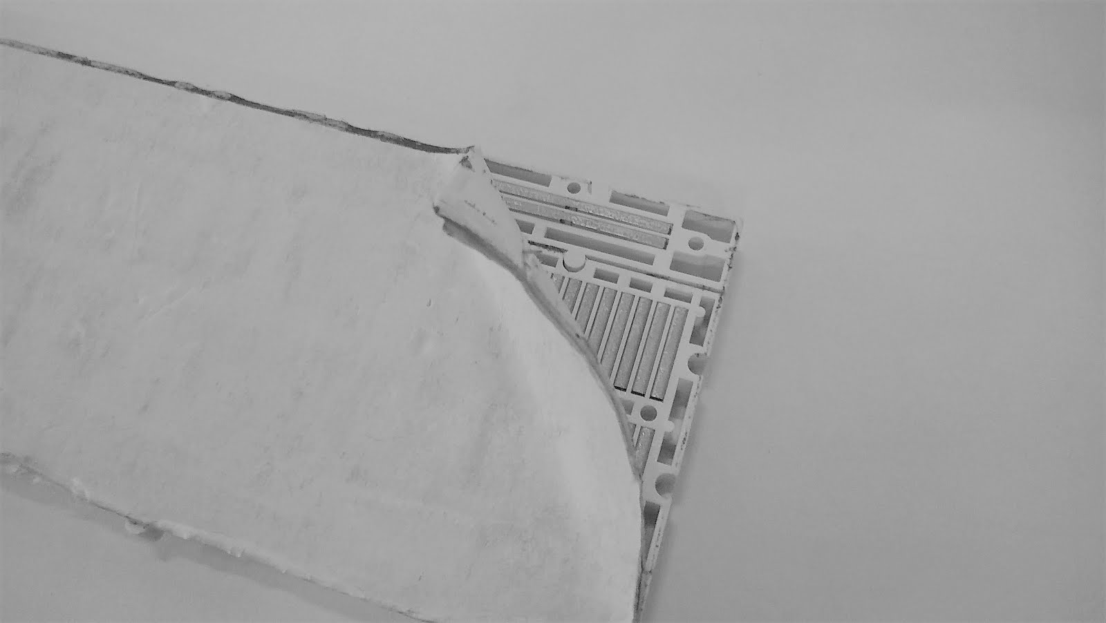
What is inside the bread board ?

Have you ever wondered whats is inside a breadboard


Own IOT website and Hardware Using Node MCU (cyber thinks)

NODE MCU code -- website link  Cyberthinks google drive link  cyberthinks website files #include <ESP8266WiFi.h> #include <ArduinoJ...